Smart Pill Reminder
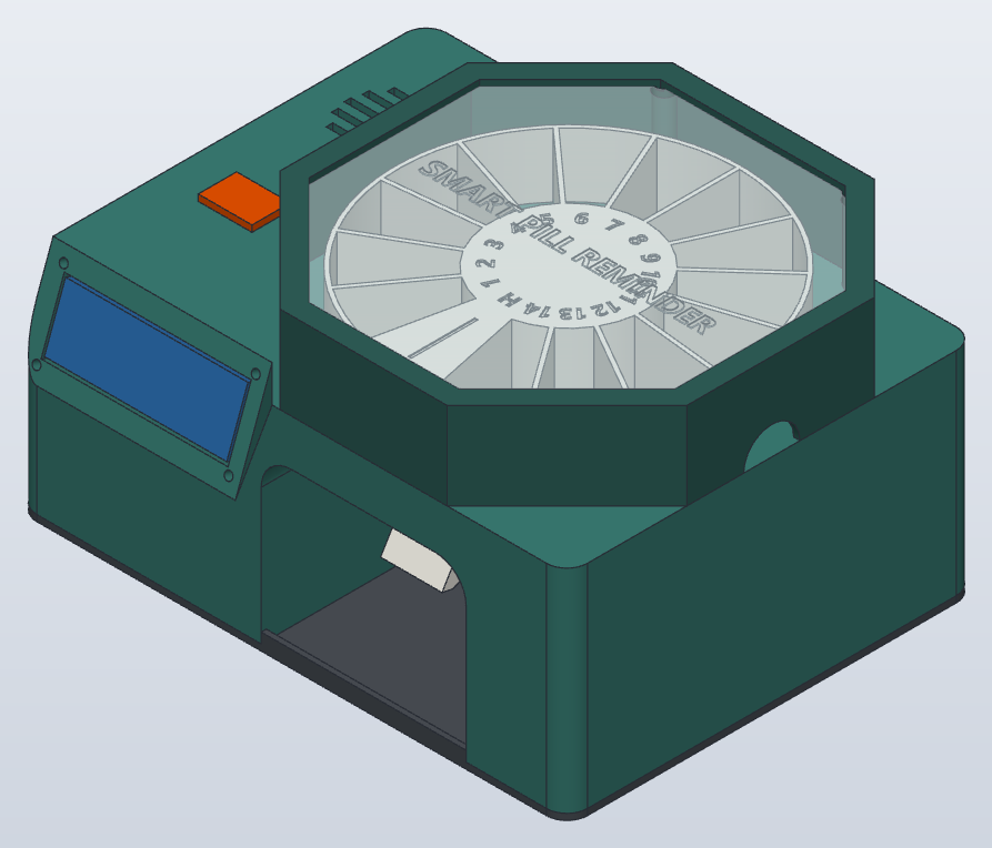
A rectangular pill dispenser with a 15-slot carousel, a talking alarm, and a cup you tip into your hand. The alarm keeps repeating until a switch feels the cup pushed all the way to its stop.
01How it works
At a dose time, the motor turns the carousel forward by one slot (24°). That slot's pills fall through a hole in the deck straight into the cup below.
The speaker plays three beeps and «حان موعد الدواء», then repeats a reminder every 30 seconds. The LCD shows
TAKE YOUR PILLS!and the phone app turns amber.The cup hangs on two pins at its top. The person slides a hand, palm up, into the opening under it (the hand cave) and pushes the small finger tab under the front of the cup back with the fingertips. The cup tips forward and the pills slide off its front edge into the palm.
Pushed all the way, the cup hits a stop at 85°. Pills start sliding out at about 65°, so by then every pill is in the hand. Only right at the stop does the cup's finger tab press the lever of a second limit switch behind the bay. That counts as "taken": the alarm stops, the device says thank you, and the family's phones get a message.
If nobody takes the pills within 30 minutes, the dose is marked missed. The next dose is not dropped on top of pills still in the cup.
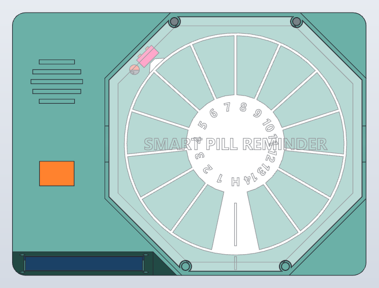
Safety rule built into the code. To find H, the carousel only turns backward, and only past slots it has already emptied. A full search turn could drop full slots into the cup, so it runs only from the "Find H (empty carousel only)" button. If the power goes off, the device remembers which slot it was on.
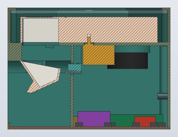
How the machine knows the pills are out. The cup can only reach its stop by tipping 85°, and pills slide out from about 65°, so a cup at the stop has poured out everything, however many capsules were in it. A second mini limit switch, the same kind as the home switch, sits behind the back wall of the cup bay. Its lever reaches through a slot into the bay, where nothing but the cup's finger tab ever gets to, and only in the last few degrees: the tab first touches the lever at about 82.5° and the switch clicks at about 84°, just before the stop. The code only counts that if the switch was open first, so a switch stuck pressed can never silence the alarm. A small push doesn't count. Pills picked out with fingers don't count either: press "I took my pills" in the app.
Why two limit switches? In the ChatGPT chat the limit switch finds the carousel's start position, and that stays the same here: a bump on the carousel clicks the switch once per turn. The second switch does the same job for the cup: it clicks only when the cup reaches full tilt. It watches the cup, not the pills, so it works the same for every pill. Unlike a light sensor, it can't be fooled by sunlight, doesn't care about the cup's colour and needs no calibration, so the TCRT5000 from the parts list is a spare again.
02Parts
From your list
| Part | Job in the machine |
|---|---|
| 28BYJ-48 5 V stepper + ULN2003 board | Turns the carousel. It sits under the deck with its shaft in the carousel's D-shaped hole. |
| Mini limit switch, 2 of them | One is HOME: it lies on the deck and is clicked by the bump on the carousel wall. The other is the full-tilt switch behind the cup bay, pressed by the cup's finger tab. Buy a second one, it is the same part. |
| TCRT5000 IR module | Not used: the second limit switch does its job. Keep it as a spare. |
| DFPlayer Mini + 3 W 4 Ω 40 mm speaker | Plays the voice files from the microSD card. The speaker sits under the grille on the top left. |
| 1602 LCD with I2C | Shows the time, doses left, and messages. It sits in the front window. |
| 20 cm female-female jumper wires | All connections, plus a small soldered power bus. |
Also needed
| Item | Qty | Why |
|---|---|---|
| ESP32 38-pin board (micro-USB), soldered to a 57.2 × 56.3 mm prototype board | 1 | None of the links is an ESP32 (me-2974 is the speaker, listed twice). The bottom plate holds the prototype board as measured; the ESP32 itself is 48.3 × 25.4 mm. |
| microSD card, 32 GB or smaller, FAT32 | 1 | Holds the voice files. |
| 1 kΩ resistor | 1 | Between ESP32 GPIO17 and DFPlayer RX. It stops a hissing noise. |
| Male header pins for a power bus | 2 × 6 | Power bus: one row for 5 V, one for GND, so three modules can share the ESP32's single 5 V pin. Solder them onto the ESP32's prototype board; the box has no separate place for a second board. |
| M3 × 10 countersunk screws + M3 nuts | 2 | Motor ears, screwed down from the top of the deck. |
| M2.5 × 12 screws + nuts | 4 | LCD, screwed in from the front. Its holes are 3.0 mm, too tight for M3. |
| M2.5 × 6 self-tapping screws | 4 | ULN2003 driver board onto its 4 posts on the bottom plate. |
| DS3231 clock module (with a CR2032 coin cell) | 1 | Keeps the time through power cuts. It runs from the ESP32's 3.3 V pin, where the board's battery-charging circuit can push almost no current into the cell, but a CR2032 must not be charged at all. So remove the charging resistor: the tiny part marked 201 in the top-right corner of the chip side, next to the small glass diode (desolder it, or ask an adult to snip it off). Don't use a rechargeable LIR2032 instead: 3.3 V can't charge it. |
| M2 × 12 screws + nuts | 4 | The two limit switches. |
| M3 × 8 countersunk screws | 4 | Bottom plate into the corner posts (they cut their own thread). |
| USB-C cable + 5 V 2 A phone charger or power bank | 1 | Plugs into the USB-C power socket at the back. A laptop USB port is too weak when the motor and speaker run. |
| 2-pin KCD1 rocker switch (6 A), red | 1 | ON/OFF. It snaps into the top of the deck, left of the lid. Mikroelectron sells it as "Red Rocker Boat Switch 2P 20mm KCD1-101". |
| USB-C female power socket, snap-in (red and black wire) | 1 | Power input in the back wall. It clicks into its hole from outside with two springy latches, so it needs no glue. Yours has no LED. |
| 3 mm clear acrylic, laser cut | 1 | The lid window, 153.4 × 154.6 mm. Take cad/laser/lid_acrylic.svg (or the .dxf) to any laser-cutting shop: red is cut, black is engraved. Keep the protective film on until you glue it. |
| Clear two-part epoxy or clear silicone | Glues the acrylic into the lid frame. Not superglue: its fumes leave a white haze on clear acrylic. | |
| PLA, about 0.5 kg | 1 | Print the carousel and cup in white or a light colour. The lid frame can be any colour, since the window is acrylic. |
| 470–1000 µF electrolytic capacitor, 10 V or more | 1 | Across the 5 V and GND rows of the power bus, long leg (+) to 5 V. It smooths the current spikes from the speaker amplifier and WiFi so the ESP32 doesn't restart in the middle of an alarm. |
| Hot glue | Speaker into its ring. The boards clip into printed holders. |
03Print
Print the five files in cad/print/X1C/, one per filament colour, in the order below. Each is already sliced in Bambu Studio for the X1 Carbon with the 0.4 mm nozzle, "0.20mm Standard" and Bambu PLA Basic, on the Textured PEI plate at 55 °C. Open one in Bambu Studio and press Print plate, or copy it to the printer's microSD card and start it from the printer's screen. Load the colour in the file's name; each plate uses one spool from start to finish.
| File | Colour | Parts, and how they lie | Print time | PLA | Supports |
|---|---|---|---|---|---|
0_FitTest | Teal | FitTest, flat | 40 min | 14 g | tree supports, only under the hinge-slot sample |
1_White_Carousel+Cup | White | Carousel, as it sits Cup, lying on its flat back | 1 h 46 min | 79 g | none |
2_Teal_Base | Teal | Base, upside down with the deck on the plate | 6 h 19 min | 268 g | tree supports under the hand opening's ceiling and the LCD window's lower edge |
3_DarkTeal_Lid | Dark teal | Lid frame, upside down | 1 h 24 min | 53 g | none |
4_Grey_Plate | Grey | Bottom plate, flat | 1 h 55 min | 84 g | none |
| Total: teal 281 g, white 79 g, dark teal 53 g, grey 84 g | about 12 h 4 min | 497 g | |||
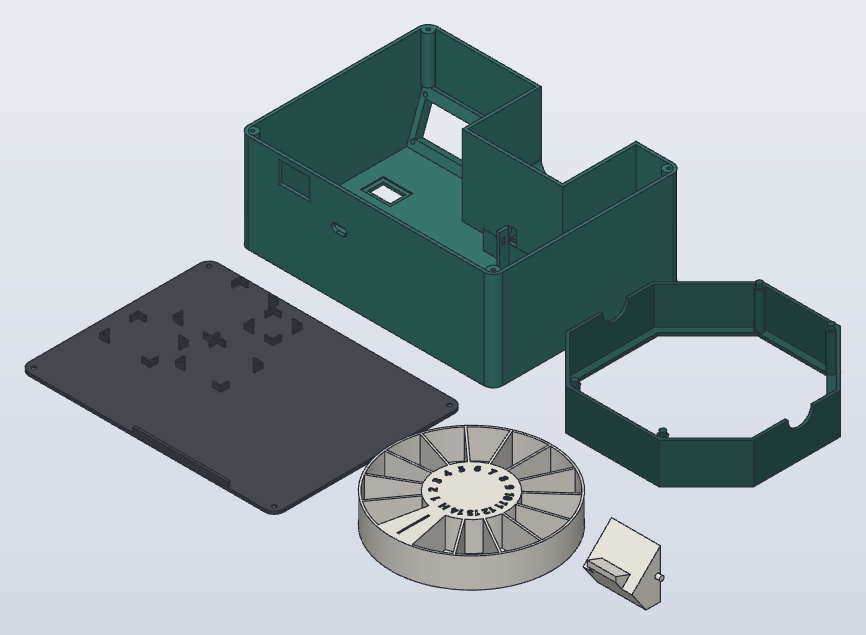
cad/build_plates.py slices the files again after a design change.Print FitTest first (40 min). Check that the LCD bezel fits the window and its 4 holes line up, the D-hole slides onto the motor shaft without wobbling, the test pin drops into the hinge slot and swings freely, the speaker presses into the ring, a limit switch's 2 holes match the slots, the rocker switch clicks into its cutout and holds, the USB-C socket clicks into its hole in the wall piece and holds, the ESP32's prototype board clicks under the snap post (and lifts out again with a fingernail), and the clock module's board slides down the rail grooves without forcing. If something is off, change that number in SolidCraft (section 10) before printing the big parts.
04Wire
This is a logical map: the pins are grouped by job, not drawn in the order they sit on the board. Read the GPIO number printed next to each pin on your ESP32.
| From | To | Notes |
|---|---|---|
| USB-C socket, red wire | Power switch, one pin | Power comes in at the back. Solder the wires to the switch pins and cover them with heat-shrink. |
| Power switch, other pin | Power bus 5 V row | Switch on = everything on. |
| USB-C socket, black wire | Power bus GND row | |
| Power bus 5 V row | ESP32 VIN | The ESP32 gets its 5 V from the bus. Its own USB port stays reachable through the back opening for uploading code: switch the power off first. |
| ESP32 GND | Power bus GND row | Every module's GND goes to this row. |
| 5 V row | LCD VCC, DFPlayer VCC, ULN2003 + | The motor, amplifier and LCD backlight need 5 V. |
| GPIO19 | Full-tilt switch NO | Its C (common) leg goes to GND, just like the home switch. GPIO19 reads LOW while the cup is at its stop. |
| GPIO21 / GPIO22 | LCD SDA / SCL | Address 0x27 or 0x3F, found automatically. |
| GPIO21 / GPIO22 | DS3231 SDA / SCL | The same two pins as the LCD: solder both wires to the same pin on the prototype board. The clock answers at 0x68 (its memory chip at 0x57 isn't used). Leave its 32K and SQW pins unconnected. |
| ESP32 3V3 | DS3231 VCC | 3.3 V, not the 5 V row: at 5 V the module would charge its coin cell, at 3.3 V almost not at all (remove the 201 resistor anyway, see Parts). Its GND goes to the GND row. |
| GPIO17 (TX2) | 1 kΩ, then DFPlayer RX | Solder the resistor in the wire and cover it with tape or heat-shrink. |
| GPIO16 (RX2) | DFPlayer TX | |
| DFPlayer SPK1 / SPK2 | Speaker | Not to GND. Keep the volume at 25 or below with the 4 Ω speaker. |
| GPIO25 / 26 / 32 / 33 | ULN2003 IN1 / IN2 / IN3 / IN4 | The motor's white plug goes into the ULN2003 socket. |
| GPIO18 | Limit switch NO | The switch's C (common) leg goes to GND. NO = normally open. |
Two things to know. The LCD's I2C board pulls SDA and SCL up to 5 V, and the clock module pulls them up to 3.3 V, so together the lines sit at about 4 V. Almost every ESP32 project runs an LCD this way without trouble, but the ESP32's pins are rated for 3.3 V. Second, the motor and the speaker never run at the same moment (the code waits for one before starting the other), which keeps the current low enough for a 2 A charger.
05Inside the machine
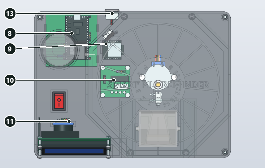
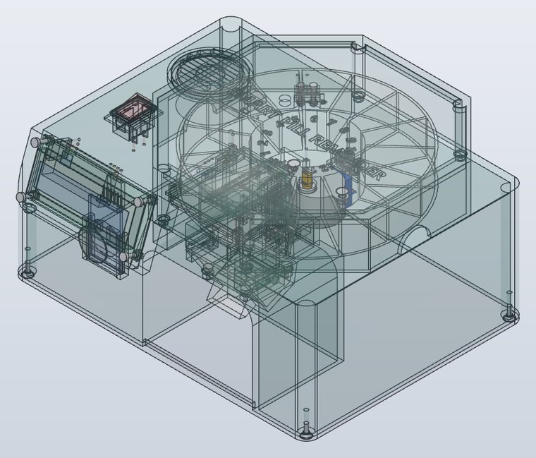
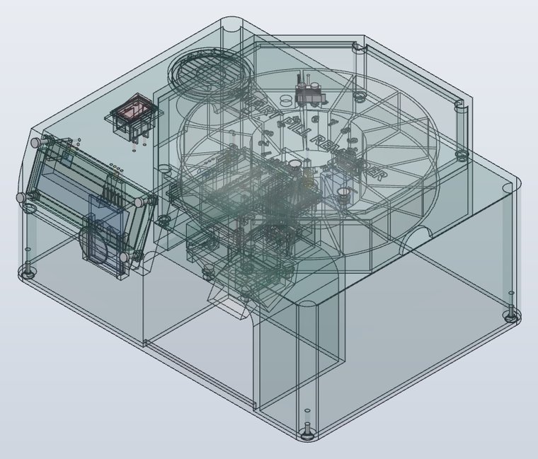
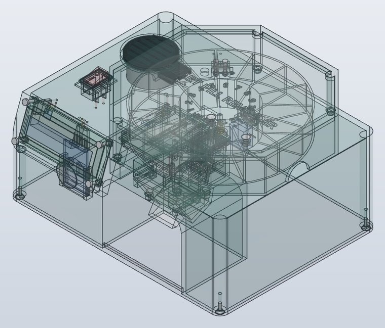
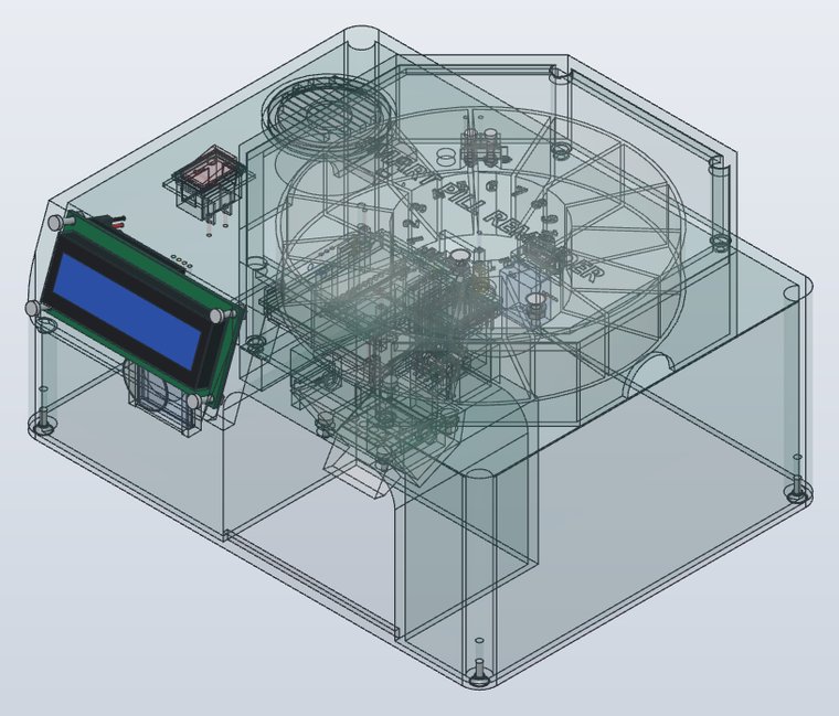
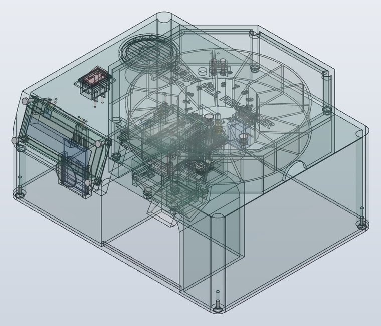
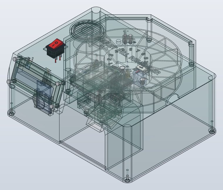
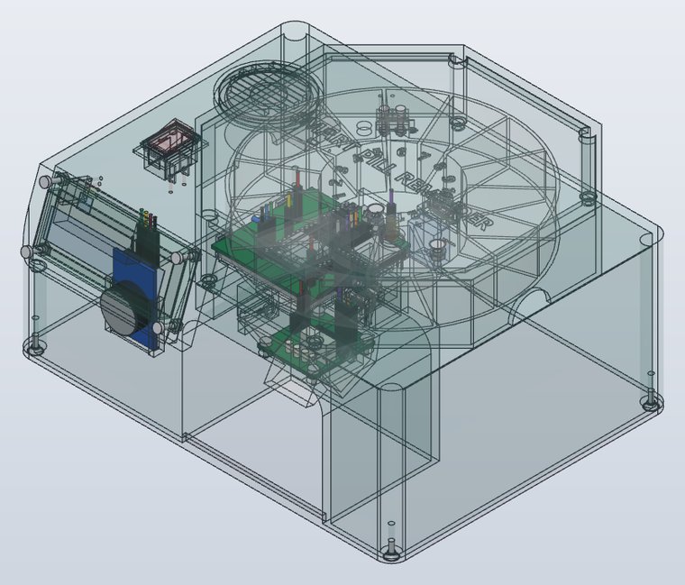
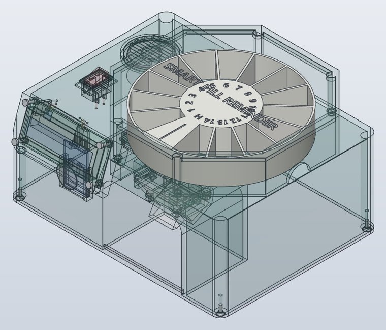
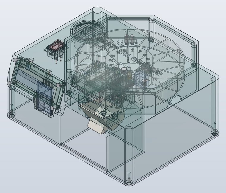
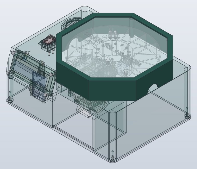
Every part in the pictures below is drawn at its real size and in its real place in the SolidCraft assembly. The printed case is drawn see-through so the parts inside show.
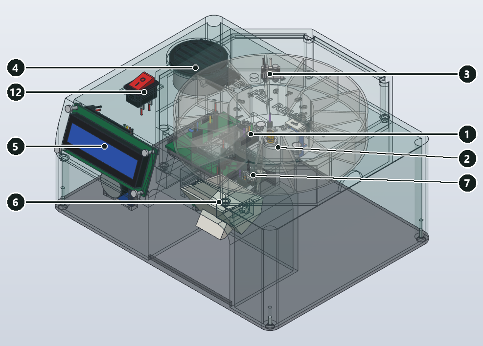
| # | Part | Where it sits | How it is held |
|---|---|---|---|
| 1 | Carousel | On the deck, under the lid | D-hole pushed onto the motor shaft |
| 2 | Stepper motor 28BYJ-48 | Under the deck, shaft up through the centre | 2 × M3 × 10 countersunk + nuts |
| 3 | Home limit switch | On the deck, back left, under the lid | 2 × M2 × 12 + nuts, in slots so it can slide |
| 4 | Speaker | Under the grille, top left | Press-fit ring + hot glue |
| 5 | LCD 1602 I2C | Sloped front-left corner, leaning back 20° | 4 × M2.5 × 12 + nuts |
| 6 | Cup | Hangs in the bay under the drop hole | Printed pins in hook slots, no screws |
| 7 | Full-tilt switch (mini limit switch) | Behind the back wall of the cup bay, its lever through a slot | 2 × M2 × 12 + nuts, in slots so it can slide up and down |
| 8 | ESP32 on its prototype board | Bottom plate, back left, USB end against the back wall at the service port | Rests on ledges, clips under 4 snap posts |
| 9 | DFPlayer Mini | Bottom plate, right of the ESP32, raised so its wires bend under it | Sits on a U-shaped stand between its two plug rows, clips in at the end away from the card |
| 10 | ULN2003 driver | Bottom plate, behind the cup bay, LEDs to the front | 4 × M2.5 × 6 self-tapping screws into posts |
| 11 | DS3231 clock module | Bottom plate, front left, standing up, pins at the top | Slides down 2 slotted rails |
| 12 | Power switch (KCD1 rocker) | Top of the deck, left of the lid | Snaps into its cutout |
| 13 | USB-C power socket | Back wall, right of the ESP32's USB opening | Clicks into its hole: 2 spring loops behind the thinned wall |
06Assemble
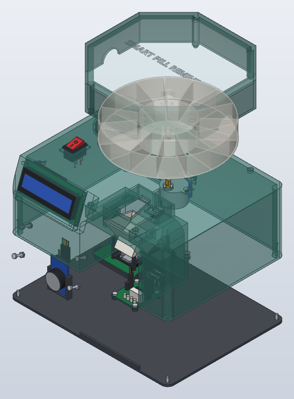
In each picture the part for that step is solid and everything else is faint.
Motor
Turn the base over. Push the motor's round shaft collar up into the centre hole of the deck, with the motor body toward the back. Put the 2 countersunk M3 × 10 screws in from the top of the deck, through the motor ears, and add the nuts underneath. The screw heads must sit flat or below the deck so the carousel can slide over them.
Home switch
On top of the deck at the back left, lay the switch flat with its lever facing the carousel and the lever's hinge end next to the round wire hole. Fix it with 2 M2 × 12 screws and nuts, its black lever-side edge on the long tick of the little scale in the deck beside it, then push its 2 wires down through the round hole next to it. Leave the screws loose until calibration.
Speaker
Press it into the ring under the grille, cone facing up, and add a few dots of hot glue.
LCD
The LCD sits close to the left wall, so first bend the 4 pins of its I2C board straight back with pliers (or solder the wires on). Then, from inside, push the LCD's metal frame into the window of the sloped front panel. Put 4 M2.5 × 12 screws in from the front and add the nuts behind.
Full-tilt switch
Behind the back wall of the cup bay, a rib hangs from the deck with two upright slots. Hold the second limit switch against the rib with its lever at the bottom, reaching forward through the slot in the wall, and fix it with 2 M2 × 12 screws and nuts, its lever edge on the long tick of the scale on the rib beside it. The front screw's nut drops into a narrow upright channel in the back wall of the cup bay, where it can't turn; the rear nut sits on the back of the rib. Leave them a little loose until calibration. Its NO and C legs get one wire each (section 04).
Power switch and socket
Push the rocker switch down into its cutout on the top-left of the deck until its clips click. The deck is thinner there so the clips can grip. Push the USB-C socket into its hole in the back wall from outside, wires first, until both latches click. The wall is thinner round the hole so the latches can grip. Solder its red wire to one switch pin, and a new wire from the other pin to the 5 V row (section 04).
Bottom plate electronics
Each board has its own printed holder on the plate, made 0.3 mm bigger than the board all round. Press the ESP32's prototype board down onto its ledges until the 4 snap posts click over it, USB end at the back. Put the microSD card in the DFPlayer first, then lay its end without the card on the post with the catch and press it down. Screw the ULN2003 onto its 4 posts with M2.5 × 6 self-tapping screws, LEDs toward the front. Slide the clock module down its two rails, battery facing the front and pins at the top.
Wire and close
Wire everything using section 04. Then lower the base onto the plate and fit the 4 M3 × 8 screws from underneath.
Carousel
Set it on the deck with its D-hole on the motor shaft. Turn it by hand until the line on slot H's roof points at the short line engraved on the deck in front of it.
Cup
Hold the cup level and pass it in through the opening. Slide its two side pins into the slots in the two lugs under the ceiling, push it all the way back, then let it drop about 3 mm into the notches. It should swing freely and come back to rest by itself, leaning back slightly. Push the finger tab under its front backward: the cup stops against two small pads under the deck. That is full tilt.
Lid
First glue in the window. Lay the lid frame upside down, peel the film off the acrylic, and drop the panel into the frame so its 4 corner notches sit around the 4 pegs. Run a thin bead of clear epoxy or silicone along the edge where the panel meets the rim, and let it set. Then put the lid on: set it down roughly in place and its 4 tapered pegs slide into the funnel-mouthed deck holes. To take it off for a refill, lift it with a finger in each of the two notches on its left and right sides.
07Program
ESP32
- Open
firmware/PillReminder/PillReminder.inoin Arduino IDE. The ESP32 board package (version 3.3.6) is already installed on this computer. - In the
config.htab, type your home WiFi name and password. - Choose Tools › Board › ESP32 Dev Module, choose the COM port, and press Upload. No extra libraries are needed.
Voice card
- Format the microSD card as FAT32.
- Copy the folder
sd_card/mp3to the card's root, so the card has/mp3/0001.mp3and so on. - Files 1–6 are Arabic and 11–16 are English. To use your own recorded voice, save it with the same file name.
| File | When it plays | Words |
|---|---|---|
| 0001 | Dose dropped | تيت تيت تيت · حان موعد الدواء · تيت تيت تيت |
| 0002 | Repeats until taken | من فضلك، ادفع أسفل الكوب حتى آخره، وخذ حبوب الدواء |
| 0003 | Pills taken | شكراً لك. تم أخذ الدواء |
| 0004 | Carousel empty | انتهت الأدوية. يرجى تعبئة الجهاز |
| 0005 | Dose missed | لم يتم أخذ الدواء في وقته |
| 0006 | Switched on | منبه الدواء جاهز |
Phone app
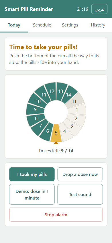
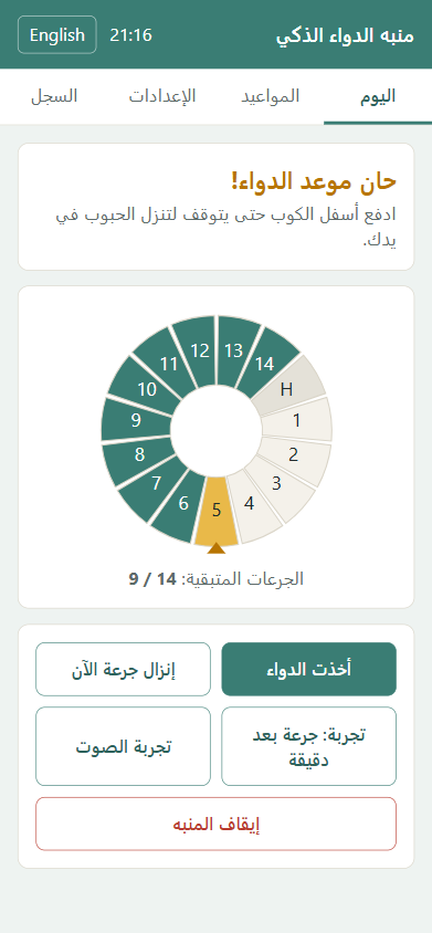
The app is a web page that lives inside the ESP32, so there is nothing to install from an app store. With home WiFi, open http://pillreminder.local or the IP address the LCD shows. If the home WiFi isn't found, the device makes its own network: join PillReminder (password pills1234) and open http://192.168.4.1. In the browser menu, choose "Add to Home screen" to get an app icon. The app works in Arabic and English. Each time it opens, it compares the device clock with the phone's and fixes it if it is more than a minute off; the clock module then keeps that time through power cuts.
| Tab | What you can do |
|---|---|
| Today | Status, next dose, a picture of the carousel showing which slots are full, and the buttons I took my pills, Drop a dose now, Demo: dose in 1 minute, Test sound and Stop alarm. |
| Schedule | Up to 4 dose times a day, each with a name. |
| Settings | Volume 0–30, voice language, repeat time, minutes before "missed", family alerts, refill, motor fine-tune, and a "Cup at full tilt" light for setting up the full-tilt switch. |
| History | The last 20 events: dropped, taken, missed, refilled. |
Family alerts. Install the free ntfy app on the family's phones, subscribe to a made-up topic name such as grandpa-pills-4821, and type the same name in Settings. The device then sends "Pills dropped", "Pills taken" and "Dose missed" messages. This needs home WiFi with internet.
08Calibrate and test
- Full-tilt switch. Open Settings › Motor and sensors. Push the finger tab slowly until the cup stops: the switch must click and "Cup at full tilt" must light just before the stop, and go off when the cup comes back a little. If it clicks too early, loosen the 2 screws and slide the switch up in its slots; if it never clicks, slide it down. Move it one tick (0.5 mm) at a time on the scale on the rib beside it: the long tick is where it is drawn, and it only works within about 1 mm of it. Then tighten. Last, tip the cup slowly with real pills in it: when the light comes on, the cup must already be empty.
- Direction. With the carousel empty, press "Find H (empty carousel only)". The carousel must turn backward (slot 1 moves away from the hole) until the switch clicks. If it turns the other way, tick "Turn the other way", save, and try again.
- Home switch. If the bump passes without a click, loosen the 2 screws and slide the switch toward the carousel in its slots. If the motor stalls on the bump, slide it away a little. Go one tick (0.5 mm) at a time on the scale in the deck beside its end: the long tick is where it is drawn, and it only works within about 1 mm of it.
- Centre slot H. After "Find H", lift the lid: the line engraved on slot H's roof must point straight at the short line on the deck in front of the carousel. If it doesn't, change "Fine-tune the H position" and press "Find H" again. About 11 steps move the carousel 1°, or about 1 mm at its edge.
- Clock module. "Clock module connected" must light in Settings › Motor and sensors. Open the app once so the phone sets the time, then switch the machine off, wait a minute and switch it on again: the screen must show the right time without opening the app. If it shows --:--, check the coin cell.
- Test run. Put a few dry beans or sweets in slot 1, press "Refill done", then press "Demo: dose in 1 minute". After a minute they should drop into the cup and the alarm should start. Slide your hand in under the cup and push the finger tab to the stop: the beans drop into your palm, the alarm stops at once, and History shows "Taken".
09Science fair demo
Power it from a power bank. Without home WiFi it makes its own network, so join
PillReminderand open the app. The clock module already knows the time; if it was never set, the phone sets it now.Show the Schedule tab, then press Demo: dose in 1 minute while you explain the carousel.
The pills drop and the alarm talks. Let a visitor slide a hand in under the cup and push the finger tab. A small push doesn't stop the alarm. Pushed all the way to the stop, the cup pours every pill into their palm, the alarm stops at once, and the app logs "Taken".
Press Demo again and wait: if nobody tips the cup, the next drop is refused because the last dose is still in the cup. That is the safety rule against double doses.
Some power banks switch themselves off when a device draws very little current. If yours does, use a wall charger at the fair.
10Change the design
Open cad/PillReminder.sc in SolidCraft. Every part shares one set of parameters, so changing a number updates all the parts that use it. Then select a part and export it as STL or 3MF. To rebuild everything at once, including the print files and pictures, run python build_cad.py --check --swing --renders in the cad folder, then python build_plates.py to slice the colour plates in cad/print/X1C/ again.
| Parameter | Now | What it changes |
|---|---|---|
| name_text | SMART PILL REMINDER | The name engraved on the lid. |
| slots | 15 | Carousel positions (1 is H). Also change SLOTS in config.h. The slot numbers on the hub are drawn for 15. |
| comp_r · car_h | 66 · 25 mm | Compartment size. |
| cup_ramp | 45° | The cup's front slope. If pills stick, try 50°. |
| lcd_win_w · lcd_hole_dx | 72.3 · 75.14 mm | Use these if your LCD differs. |
| shaft_d · shaft_flat | 5.25 · 3.2 mm | Use these if the carousel is loose or tight on the motor shaft. |
| sw_hole_sp · sw_hole_in | 6.51 · 4.95 mm | Home switch screw holes. |
| lever_out · lever_gap · lever_pre | 2.33 · 3.9 · 2.07 mm | Your limit switch's lever: how far its tip reaches past the body, how far it hangs below the body, and how far it moves before it clicks. build_cad.py places the full-tilt switch from these so it clicks at TILT_CLICK (84°). |
| kcd_w · kcd_h | 18.9 · 12.1 mm | Cutout for the power switch: its measured body plus 0.2 mm a side. Its clips are ridged tabs that grip a range of thicknesses, so the deck round the cutout is thinned to 1.7 mm (kcd_panel). Check it on the FitTest before printing the base. |
| usbc_w · usbc_h | 13.7 · 5.8 mm | Hole for the USB-C power socket: its measured body plus 0.2 mm a side. Its two latches are V-shaped spring loops on the short ends whose slope starts just behind the flange, so the back wall round the hole is thinned to 1.2 mm (usbc_wall), where that slope presses the flange tight. Check it on the FitTest before printing the base. |
| tab_h · tab_w · tab_lean | 5 · 24 mm · 20° | The finger tab under the cup: how far it hangs down, how wide it is, and how far its face leans toward the hand. Past about 8 mm it hits the back of the bay at full tilt, so run python build_cad.py --swing after changing it. |
| cave_w · cave_r | 80 · 12 mm | The hand cave: its width, and the radius of its two top corners. It is centred under the cup so the pills land in the middle of the palm, and runs up to the cup's rest ledge, 65 mm. |
| acr_t · lid_rim | 3 · 8 mm | Acrylic thickness and the width of the lid frame. build_cad.py writes new laser files to cad/laser/ every time it runs. |
| lid_cut_f · lid_cut_b | 46.8 · 40 mm | How much the octagonal lid cuts off its front and back corners. The front cut keeps the LCD corner free and the back cut clears the home switch. build_cad.py stops with a message if a cut would bring the lid into the carousel's path. |
| LCD_TILT | 20° | How far the LCD leans back, set at the top of build_cad.py. |
| TILT_STOP | 85° | How far the cup tips before it hits the stop. It is set at the top of build_cad.py, which then moves the stop pads and the full-tilt switch to match. |
| cup_vee · cup_vee_y | 35° · 17 mm | The cup's V floor. After changing the cup, run python build_cad.py: it works out the cup's resting angle again and moves the stop pads and the full-tilt switch to match. |
Parameters whose note says MEASURE are typical sizes. Check your own parts with a ruler or calipers.
11Check before you build
Already checked on the computer
SolidCraft found no overlap between any printed part and real-size stand-ins for the motor, LCD, speaker, ESP32, DFPlayer, ULN2003, DS3231 clock module, power bus, power switch, USB-C socket, the acrylic lid panel, and the home and full-tilt switches with their levers. That includes the LCD leaning back 20° in the sloped front-left corner and the octagonal lid centred on the carousel, whose walls stay at least 5.6 mm outside the path of the carousel's home bump and whose cut back-left corner clears the home switch by about 3 mm. SolidCraft also tipped the cup to 45°, 70° and 84.5°: it clears the deck, the carousel and the motor at every angle, and at 84.5° its only contact is the finger tab pressing the full-tilt switch's lever, as intended. At 86° it overlaps the base only at the two stop pads, so the pads are what stops it. A separate calculation of the tab's path puts the first touch on the lever at 82.5°, the click at 84° and about 1.5 mm of lever push at the stop, without the tab ever reaching the switch body. When the cup hits the stop, a push on its bottom presses the hinge pins down into their notches, not up and out. Every part fits the X1's 256 mm bed. The firmware compiles for ESP32 Dev Module (core 3.3.6). The voice files contain speech (checked by loudness, not by ear), so listen to 0001.mp3 once before copying it to the card.
Not tested yet: needs the real parts
Nothing has been printed or powered up. The angle at which the pills slide out of the cup depends on the pills: about 65° of tilt with the 45° front, and the stop is at 85°. Test with your own pills that every one is out before the switch clicks. Sticky gel capsules on a humid day are the risk. The exact click point depends on your switch's lever, so set it in its slots (section 08). The board sizes and hole spacings are typical values, which is why FitTest exists. The clock module code compiles but has never run on a real board, so do the clock check in section 08. After printing, push the cup to full tilt by hand and make sure its pins stay in their notches. Try the hand cave with the hand of the person who will use the machine: 80 mm wide fits most adult hands palm up, and cave_w changes it. The switch and socket sizes are taken from typical parts, so check the FitTest pieces with yours. Order the acrylic in the thickness you can actually get: if it isn't 3 mm, change acr_t before printing the lid.
Ideas for version 2. Add a small servo gate that drops one pill at a time from a bigger compartment, which was the idea in the ChatGPT chat. Add a second tray stacked on top.